End tabbing of composite test specimens – Theory

In a previous article, I have covered why we do not use dog bone shaped specimens when testing composites. In order to ensure we get gauge length breaks, as a test lab we instead turn to end tabbing.
There seems to be a sense of unnecessary mystery in the composites industry surrounding the end tabbing of composite test specimens. This view is not helped by the following statement in ASTM D3039-17 for tensile testing [1]:
The reality however, is that there is something of an industry consensus on how to end tab specimens. I will go into further detail as to why I do not categorically state that there is a definitive way, as there are some small differences between laboratory methods. Despite this, best practice tabbing of composite materials can be found in DOT/FAA/AR-02/106 Tabbing Guide for Composite Test Specimens [2].
Why do we end tab?
Before we delve into the how, lets first explore why end tabbing of composites is necessary. Assuming that wedge grips are used, at a typical wedge angle of 10°, the through-thickness clamping force applied on an untabbed specimen will be 28% higher than the applied tensile force. This causes a significant stress concentration at the edge of the grips. To counter this and to promote a failure in the central gauge section of a specimen, tensile specimens are usually dog boned in shape. However, as covered in a previous article, this isn’t possible for composite materials, so an alternative way of alleviating the stress concentration is required. An additional consideration is the damage that the grip serrations cause to the surface of the composite. These are usually sufficiently aggressive that they can break through the resin-rich outer surface and damage the underlying load bearing fibres. With this in mind, it is clear that both the stress concentration needs to be limited and the surface protected.

Figure 1 -Wedge grips principle
That is not to say that end tabbing is always necessary. As a rule of thumb, the more orthotropic a material is, and the higher the strength, the greater the need for end tabbing becomes [3]. Additionally, the higher strength the material, the more impact end tab design has on the test results. It is perfectly reasonable not to end tab fibreglass constructed from chopped strand mat for example, as it’s relatively low strength and irregular fibre distribution, can promote gauge length failures without the need for any additional measures. Similarly, it may be possible to use a sheet of emery cloth as the cushion between the grips and the specimen for intermediate strength composite materials. However, with unidirectional composites, end tabbing becomes a necessity.
What material should we use?
Material choice for end tabs can influence both the measured properties and the ease of use through future operations. The chosen material should be as compliant as possible, without losing the strength necessary to transfer the load from the grips to the specimen’s gauge section. It must also be sufficiently tough to withstand the harsh tearing action of the grips.
Metallic end tabs have a long history of use with composite test specimens, with carbon steel or aluminium being the preferred metallic material. Both of these materials have issues though. The high toughness of steel, means that when machining specimens with pre bonded steel tabs, the tabs will pop off. This means that the only way to accurately tab specimens with steel is to tab specimens after machining. Tabbing in this way is incredibly time consuming and to guarantee the alignment a special fixture must be used. While aluminium end tabs do not suffer with popping off in the same way, aluminium requires special surface treatment to prepare it for bonding. Due to the oxide film that forms on aluminium, a chemical etch is required to promote bonding. This involves the use of chromic acid or phosphoric acid to remove the oxide film prior to bonding. Extreme caution must be used when using chromic acid, as there are significant health concerns related to its use.
The most commonly used tabbing material is fibreglass printed circuit board material, ideally in a +/-45° orientation. The material is easily bonded to the composite panel and does not pop off during machining. The relatively low stiffness of the fibreglass in this orientation helps to minimise the tab termination stress concentrations and it is sufficiently soft to allow the grips to bite into the surface of the tab. Printed circuit board material is also relatively low cost and is readily available in various thicknesses. An additional benefit of using fibreglass end-tabs is the material is translucent and any gaps in the glue line can easily be seen by visual examination. In concluding their review of tabbing materials, Adams and Adams concluded that “Glass fabric/epoxy should be considered as a tabbing material unless there is a clear reason why another material is preferred [2].”
The final material option for tabbing is carbon fibre. Carbon fibre is an expensive tabbing material and the additional stiffness of the carbon fibre means that it doesn’t have the same stress concentration reduction capabilities as fibreglass.
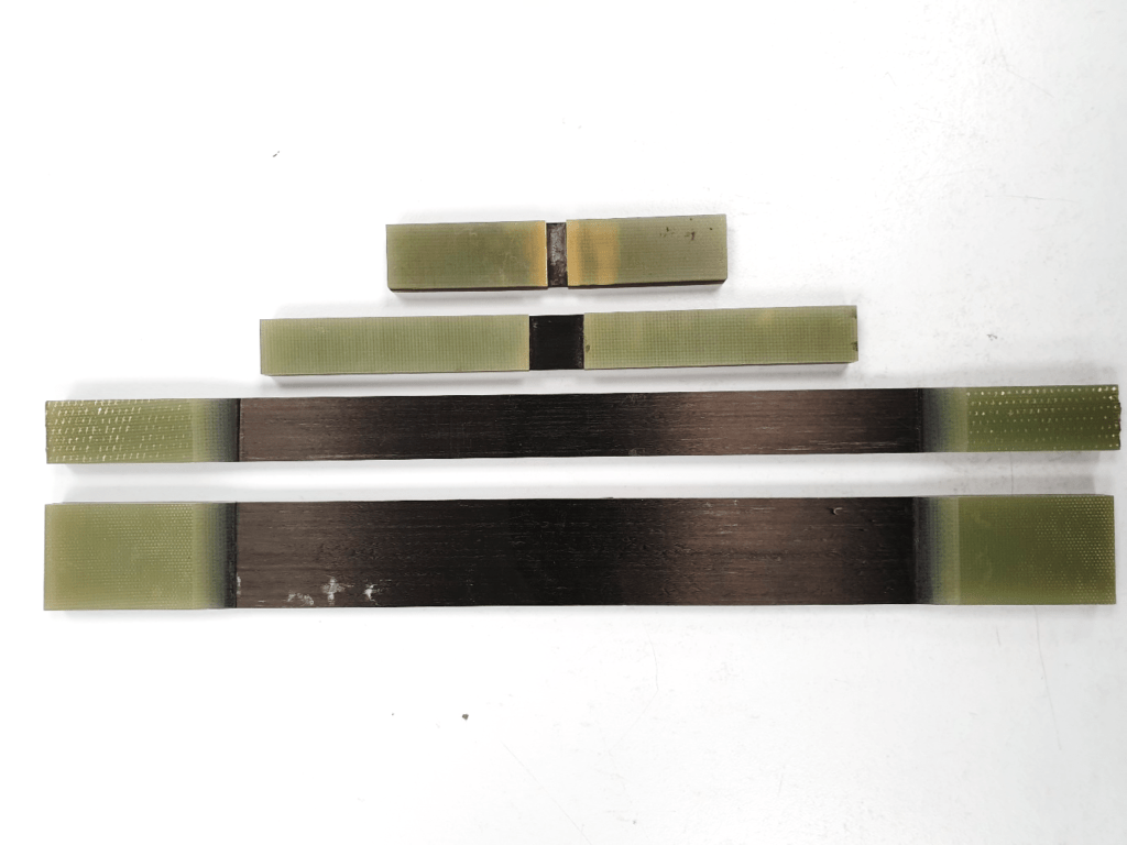
Figure 2 – A selection of samples with fibreglass end tabs
Adhesive choice
As the tensile load is introduced into the specimen via shear, it is important to choose an adhesive that has a suitably high shear strength. The old CRAG standard specified that the adhesive used should have a shear strength of more than 30MPa [4]. Beyond that, the choice of adhesive is driven by the user and the Tg of the material being tested.
Film adhesives are generally easier to use and give a controlled bond-line thickness, however they require an elevated temperature and pressure to cure. This is either achieved through a hot press, or by vacuum bagging within a curing oven. In some cases, the cure temperature of the adhesive is greater than the Tg of the test material, in which case, using a film adhesive can have a deleterious effect on the mechanical properties.
Alternatively, a two part epoxy paste adhesive can be used. These do not require any additional equipment to use and can be cured at room temperature, negating any concerns over the Tg of the material, however steps need to be taken in order to control bond-line thickness.
End tab design

Figure 3 – End tab design
A final consideration when it comes to tabbing material is the design of the tab itself. Generally speaking the tab should be the same width as the test specimen and for tensile testing it should be at least 40mm long and up to 90mm long. The length chosen in that range depends entirely on the length of the wedges in the grips of the machine you are using.
While ISO 527-4/5 categorically state that a 90° tab termination angle should be used [5], ASTM D3039 is more nuanced in its approach to this. This is due to research which has shown that using tabs having a tapered termination angle of between 10-15° can exhibit an increase in tensile strength of up to 18%. This is because tapering the tabs reduces the stress concentration at the tab termination region and thus, promotes failures within the gauge section. Shallower angles than 10° however are not recommended, as this leads to the tabs peeling off during testing [3].
Conversely, when compression testing of laminates, it is recommended not to taper the tab termination area. The reason for this, is that the potential for buckling has more of a bearing on results than the stress concentration caused by the tab termination region. We therefore compromise on the design in compression, in order to minimise the effects of buckling on results. More information on this can be found in the previous article “A Practical Guide to Compression Testing of Composites.”
Finally, the thickness of both the adhesive and the tabbing material has an affect on test results. Both materials act as a cushioning layer, with the closest to the material, the adhesive having the greatest effect. As a rule of thumb, a tab thickness of 1.5-2mm thick and a bond line thickness of 0.5-1.3mm generally deliver optimum results, while avoiding the additional cost of using more material.
References
- ASTM D3039/D3039M-17 Standard Test Method for Tensile Properties of Polymer Matrix Composite Materials
- Adams D.O. & Adams, D.F. DOT/FAA/AR-02/106 Tabbing Guide for Composite Test Specimens, October 2002
- Don Adams, Tabbing composite test specimens, when and why, Composites World, 2011
- Hodgkinson, J.M. Mechanical testing of advanced fibre composites, CRC Press, 2000
- BS EN ISO 527-5:2019 Plastics – Determination of Tensile Properties, Part 5: Test conditions for unidirectional fibre-reinforced plastic composites.