In the world of fibre composite testing, alignment is king. Unlike metals, which are isotropic in nature, the properties of composites vary significantly according to the directionality of the specimen’s fibres. Furthermore, in compression testing, any sources of misalignment can induce buckling, producing invalid results regardless of the specimen appearing to fail by a valid failure mode.
All this means that ensuring and maintaining alignment throughout the whole test set-up, is the only means of delivering good quality, repeatable results.
Now you might be thinking, ‘well how hard can it be?’. We have all seen photos of drastically wonky samples being tested by inexperienced and naïve technicians. But don’t be fooled, guaranteeing alignment takes a lot more than just a good chunk of common sense, and in some cases, satisfactory alignment can be impossible to achieve.
Here are 4 areas to straighten out in your test method to guarantee reliable, high quality, consistent test results.
Fibre Alignment and Specimen Machining:
Fibre misalignment is generally introduced due to a lack of care and detail during machining. Failing to ensure that samples are machined such that the fibres are oriented perfectly can lead to a reduction in measured values.
A 1° misalignment of the fibres leads to fibres terminating off the edge of your specimen prior to the end of the sample. These fibres that were intended for load bearing will therefore be unable to bear the loads required of them, ultimately reducing the load bearing capacity of the specimen and delivering reduced results.
Alongside diminished reported strengths, misaligned machining also results in an uneven stress distribution amongst the remaining fibres, leading to premature failures in the high stress region, illustrated by figure 1.

Figure 1 – Stress distribution due to misaligned fibres
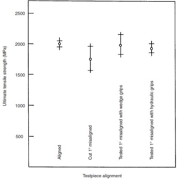
The effect of misalignment can be seen in a graph taken from the book Mechanical Testing of Advanced fibre composites in figure 2. Not only does misalignment deliver reduced results, but also a significant increase in the standard deviation of the results. Bizarrely the standard deviation caused by a misaligned specimen is reduced by using side acting hydraulic grips in comparison with wedge grips, however it is clear that it leads to a reduction in the measured tensile strength.

Figure 2 – The effect of misalignment on tensile strength of composites
So how do we guarantee that we machine our samples in such a way that we get well aligned fibre?
Aligning unidirectional composites can be easily achieved by using what is called the ‘chocolate bar’ snap test. Using the edge of the bench, you can snap the bar along the length of the fibre, due to the unsupported matrix between the fibres being so brittle. With a non-unidirectional specimen, things aren’t quite as straight forward however. The only way to guarantee this alignment would be by visibly tracing the fibre direction and marking it with an indelible marker. This line can then be used as a reference for machining.
Grip alignment
You have now spent a great deal of care to make sure your samples are aligned, however this can all be undone by a poorly aligned machine. Misalignment of the load train or the specimen leads to non-uniform force application resulting in additional bending or twisting forces being imparted on the specimen and erroneously low breaking forces.
This is why many tensile standards, such as ASTM D3039 and ISO 527, require you to prove the alignment of your machine during testing by using a strain gauged specimen. The methods outlined in both standards require that three strain gauges be placed around the midpoint of a specimen, two on the front face and one on the rear face to measure the bending stresses applied on your specimen during the modulus determination range. In order to produce a valid test, the applied bending in any direction must not exceed 5%.
Moving into the world of testing for aerospace applications and the requirements become more stringent again. Nadcap stipulate that the alignment of your testing machine meets the requirements of ASTM E1012. In this standard mis-alignment is defined as “the greatest difference in axial strain under load between the average strain (of 3 or 4 strain gauges in any circumferential set) and any individual gage in that set, divided by the average strain, times 100. Using a specimen with a minimum of 8 strain gauges, the recorded mis-alignment of all directions combined must not exceed 8% when testing composites. A great deal of attention must go in to ensuring the grips are correctly set and if the load train changes for whatever reason, for example by changing the grips being used, the alignment must be verified again.
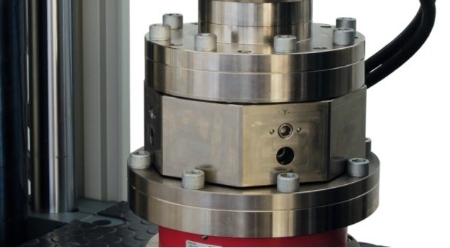
Traditionally small degrees of misalignment could be over come by the use of carefully placed metal shims, however this involves a great deal of time and effort. These days, some machine manufacturers have helped ease the pain by producing and alignment fixture. This fixture allows for fine adjustments of the alignment in each direction to give the highest possible degrees of alignment. An example of which can be seen in figure 3 below. Some manufacturers even provide a software package to accompany the fixture, which allows you to easily determine the precise amount of adjustment needed based on the results given by ASTM E1012.

Figure 3 – Zwick grip alignment fixture
Specimen gripping

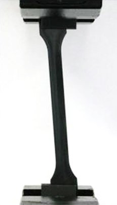
Figure 4 – Example of a specimen misaligned within the grips of a tensile machine
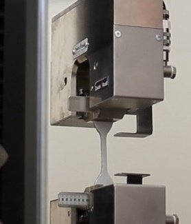
So, you have made sure that your fibres and your grips are aligned, but that is only half the battle. If your specimen is misaligned within the grips, it can undo all the good work of ensuring your grips are aligned and some. One way to ensure the specimen is aligned within the grips is by eye, but this can be quite unreliable and time consuming. Another more consistent approach is to use physical back stops. You can set you back stops to the required distance and by placing the sample in up against the back stops, you can ensure that the specimen is perfectly aligned every time. An example of this can be seen in figure 5.

Figure 5 – Example of back stops used for specimen alignment.
Strain Gauging
Finally, you have done everything you can to test your samples with perfect alignment, but the struggle doesn’t necessarily end there! Strain gauging can be another pitfall of misalignment. Errors of 15% can arise from a 2°degree misalignment of a strain gauge. Great care must go into ensuring the correct alignment of a gauge on the specimen. This is where is becomes essential to have highly trained technical staff to carry out the strain gauging, or to outsource to a company that specialises in applying strain gauges, as strain gauging of composites can be difficult. This can be helped by the use of larger gauges however.
In summary, if you want to produced accurate and reliable results, you need to minimise all potential sources of misalignment. The combined errors introduced can have significant effects on the measured results.
To find out more about factors which can negatively effect your testing results, please check out our previous articles on why aren’t composite tensile samples dog bones, when does a composite flexure test become an interlaminar shear test and strain gauging of composites – dark art or simple science? Additionally, sign up to our popular training course on mechanical testing of composite materials.
References
- J M Hodgkinson – Mechanical Testing of Advanced Fibre Composites, Woodhead Publishing, 2000
- D O Adams & D F Adams – Tabbing Guide For Composite Test Specimens, US Department of Transportation Federal Aviation Division, report DOT/FAA/AR-02/106, 2002
- ASTM D3039/D3039M-17 – “Standard test method for Tensile Properties of Polymer Matrix Composite Materials”
- BS EN ISO 527-4:1997 – “Plastics – Determination of tensile properties – Part 4: Test conditions for isotropic fibre-reinforced plastic composites”
- ASTM E1012 – 14 – “Standard Practice for Verification of Testing Frame and Specimen Alignment Under Tensile and Compressive Axial Force Application”