Compression testing of composites can be a minefield. With countless different standards based on three different means of load introduction, many fixture variations and a seemingly endless multitude of standards. But which is the ultimate compression testing method and what pitfalls should you look out for? Despite decades of research and use, no one compression test method has become generally favoured by the composites community. How has this situation come to pass, when the options for tensile testing are so straightforward.

Figure 1 – Clockwise from top left, IITRI (Wyoming Test Fixtures), Celanese (Instron), Mixed mode compression (Instron), modified D695 (Zwick Roell) and NASA end block (Jooshin Industrial Co.) compression fixtures
Metals exhibit the same properties in both tension and compression and in the early days of composite technology, the belief was held that composites should do the same. However, when experimental results didn’t reflect this assumption, rather than question the science, technologists concluded that there must be something wrong with the compression test method. Researches would then go away and develop another method. Samples would be seen to buckle at what was believed to be premature failure and a whole host of anti-buckling solutions were developed in order to prevent Euler column buckling. Despite the development of these anti-buckling fixtures, the compression strengths remained significantly short of the tensile strengths.
In fact the truth behind the lower compression strength is actually caused by a difference in failure modes. In tension, the failure is caused by an overload of the fibres, while in compression we see micro-buckling of the individual fibres.
This micro buckling is due in part to the difference in thermal expansion properties of the fibre and matrix during curing. A typical thermal expansion of a matrix is 70µε/°C, while the fibre would typically be -5µε/°C. This difference in thermal expansion leads to the fibres becoming slightly wavy during curing. In tension, these fibres straighten up and are able to experience their full load capacity, but in compression this waviness encourages micro-buckling [1]. This micro-buckling is not to be confused with Euler Buckling, which is a macroscopic phenomenon.

Figure 2 – Microbuckling failure observed during composites compression testing [2]
During the period of doubt and discussion around this issue, a number of methods gained seniority over others, but in the early days, these methods were not without their problems. To ensure consistency in load application and ease of use, the standard ASTM D695 fixture, which was used for plastics testing, was modified to include an L-shaped stand, attached via mechanical fasteners [3]. This became known as the Boeing modified ASTM D695 (despite not actually becoming recognised as an ASTM standard in itself), which underlined the end loading method also used for EN 2850 and SACMA SRM 1. One of the downsides of this method was that the consistency of the test results was influenced by how tightly the fasteners were torqued. An overly torqued fixture can lead to a significant friction effect through a redundant load path, giving excessively high strength results. Due to this, the Boeing procedure recommends that the fasteners should be torqued between 0.68 and 1.13Nm.
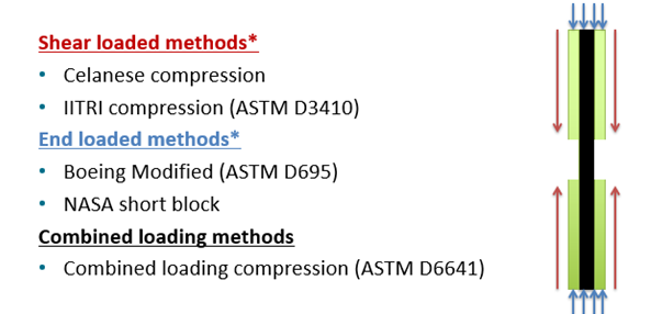
Figure 3 – Summary of methods using either shear, end or combined loading methods and their load introduction technique
Similarly the first standardised compression test method, the Celanese shear loaded method used in ASTM D3410 was also not without it’s faults. The method essentially used an inverted wedge grip system, that increased the clamping forces as the compressive force increased. As the load is introduced through side acting wedge grips, the compressive force is introduced onto the end tabs of the composite specimen through a shear action. The challenge with the Celanese design was the lack of alignment rods meant it was easy for the wedges to become misaligned and introduce a bending stress on to the specimen, promoting a premature failure [4]. This issue was overcome through the presence of alignment rods in the IITRI fixture but eventually these misalignment issues saw the Celanese fixture removed from the ASTM D3410 standard in recent years.
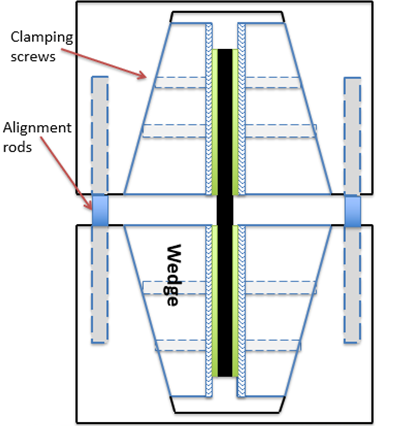
Figure 4 – Schematic diagram of the IITRI shear loaded compression fixture used for ASTM D3410
During the 1990’s, in reaction to the perceived downfalls of the end loading and shear loading methods, the combined loading test method was developed. The theory behind this method is that by introducing the load through both the end and through shear, there is a reduction in the stress concentration introduced, giving more consistent results and minimising the deficiencies of each loading method [5-6]. At around 5kg in weight, this also leads to an easier to handle and lighter weight fixture than the IITRI fixture, which weighs around 40kg. The level of shear introduced can be controlled by the level of torque applied to the clamping bolts, with the minimum amount of torque to prevent end crushing failures being recommended. Generally this torque level is specified as being between 2.5-3Nm, however this can be increased if excessive end failures occur. It is not recommended to tighten the bolts to an excessive torque, as there are no positive benefits and it only serves to increase the detrimental clamping forces, which increase the stress concentration in the gauge area and causes through thickness distortion of the test specimen [8] .
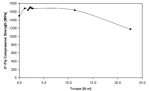
Figure 5 – Effect of bolt torque on measured compressive strength using combined loading compression fixture [8]
All of this history and theory is nice, but which method actually gives the best results? Well the answer in short is all of them! A number of studies have been conducted comparing the results obtained using the IITRI and the modified ASTM D695 method and have showed they largely deliver the same results when used correctly [7]. Likewise, a similar initial study comparing the combined loading compression method with the IITRI method on a small number of samples showed similar results [8]. This highlights the golden rule of compression testing of composites: It is not what method you choose, so much as ensuring it is used correctly that leads to accurate and reliable test results.

Figure 6 – Compressive strengths of various unidirection carbon/epoxy composites as a function of slenderness ratio using different test types [7]
In light of this, what parameters should we pay close attention to when compression testing that can influence results?
With end loading compression, the flatness and parallelism of the ends of the samples, along with that of the compression platens is of vital importance in order to ensure an even load transfer across the ends of the samples. This is why standards often state a requirement that the ends of the samples and the working area of your compression platens should be flat to within 0.02mm. If the samples aren’t parallel, you will end up with the load transfer being off axis in comparison to the fibre direction, which will promote bending and a premature buckling failure.
Likewise, with shear loaded compression samples, the flatness and parallelism of the tabbed surfaces on the side of the sample are of upmost importance. Again, this is in order to prevent excessive bending.
It is highly recommended that back to back strain gauges are used on compression samples to ensure excessive bending does not occur. Unfortunately, strain gauges are the only reliable way to detect bending, as visual or microscopic examination is unable to give a reliable indicator of bending during testing. But how much bending is too much? Well, even though the ASTM standards acknowledges that bending strains of up to 40% may not significantly affect the measured compressive strength, a test is only considered valid if bending strains are less than 10% [9]. This is to ensure that your sample preparation and machine/fixture alignment is of sufficient quality to deliver consistent results.

Figure 7 – Suddenly diverging strain gauge readings indicating buckling failure [7]
Another consideration that is often overlooked is the hardness of the compression platens. Insufficiently hardened platens will deform over time and lead to uneven load transfer at the ends of the samples. In practise this leads to end crushing rather than gauge length failures. For this reason, it is recommended that the compression platens are regularly checked for any sign of excessive wear or damage.
One thing that the wide range of compression test methods have in common is the use of a very short gauge length. Typical gauge lengths for compression samples are 10-13mm, although they can go as low as 5mm. In comparison, the typical gauge length of a tensile specimen is around 160mm. This is due to the requirement to minimise a premature buckling failure.
But what is the ideal gauge length to deliver the highest measured compressive strength for your samples? In truth, the shorter the gauge length the better, as it minimises the possibility of buckling failures caused by poor specimen preparation. This is where the old SACMA SRM 1 & EN2850 standard come into their own. Unfortunately, the SACMA standard has not been updated since 1994 and with SACMA having disbanded in 1999 [9] is unlikely to be updated in the future.
There are, however, drawbacks to using short gauge lengths. Gauge lengths shorter than 10mm mean that a separate specimen needs to be used for strength and modulus determination, as it is incredibly difficult to bond a strain gauge accurately on this scale.
It is worth noting that, while tensile samples perform best with a tapered tab termination region, this is inadvisable for compression samples. While the benefits of a tapered tab in reducing the stress concentrations at the tab termination area are clear and well researched, the requirement to prevent micro buckling failures outside of the gauge length is of greater significance. For that reason, it is preferred that samples are not tapered in order to offer full structural support to the sample outside of the gauge area. Due to this, the majority of compressive failures occur at, or very near to the tab termination region. One way of reducing the tab termination stresses however is to use a thicker adhesive bondline, with adhesive layer thicknesses of 0.3-1.3mm recommended [10].
One final consideration is the thickness of composite test specimens. As thin rectangular specimens are used for testing, these are typically prone to buckling failure. In order to overcome this, a minimum specimen thickness is required, which can be calculated from the equation given in ASTM D3410 and ASTM D6641M, based on the gauge length, the expected compressive strength, the compressive strength of the fibre, the fibre volume fraction, the expected flexural modulus and the expected through-thickness shear modulus (We told you it can be a minefield!). When buckling failure occurs, the only thing that has been determined is that the compressive strength of the material is higher than the stress at which buckling has occurred.
In summary, as long as your sample preparation and test set up is such that you can get consistently reliable test results from the fixture you are using, then the best compression test method is the one that works for you. At R-TECH Materials we are accredited by UKAS to perform compression testing to a multitude of standards and would be happy to help you with your compression testing enquiries.
References
[1] IRT Saint Exupéry. (2018). Graphene in Composites, unexpected science from a pencil trace by Constantinos Soutis. [Online Video]. 6 September 2017. Available from: https://www.youtube.com/watch?v=HDxv40K6Dk8. [Accessed: 4 April 2018]
[2] Lemanski SL, J Wang, Sutcliffe MPF, KD Potter, MR Wisnom. Modelling failure of composite specimens with defects under compression loading. Composites A (2013)
[3] Adams, D. (2007). Testing Tech: The Modified D 695 Compression Test Method. Composites World. [online] Available at: https://www.compositesworld.com/articles/testing-tech-the-modified-d-695-compression-test-method [Accessed 20 Aug. 2018].
[4] Adams, D. (2017). Test Methods for Composite Materials.
[5] ASTM D6641M-16 Standard Test Method for Compressive Properties of Polymer Matrix
[6] Carlsson, L. Adams, D. & Pipes, R. (2014). Experimental characterization of advanced composite materials. 4th Florida: CRC Press pp.131-145
[7] Charterjee, S. Adams, D. & Aplinger, D. (1993). Test methods for composites a status report volume II. Compression test methods. FAA Technical Center
[8] DOT/FAA/AR-00/26 Verification of the combined load compression (CLC) test method
[9] Adams, D. (2014). Bending of composite material compression specimens. Composites World. [online] Available at: https://www.compositesworld.com/articles/bending-of-composite-material-compression-specimens [Accessed 20 Aug. 2018].
[10] O’DAY, P. (2011). Time for a new “SACMA”. [online] Compositesworld.com. Available at: https://www.compositesworld.com/columns/time-for-a-new-sacma [Accessed 20 Aug. 2018].
[11] Adams, D. and Adams, D. (2018). DOT/FAA/AR-02/106 Tabbing Guide for Composite Test Specimens. [online] Washington: U.S. Department of Transportation Federal Aviation Administration. Available at: http://www.tc.faa.gov/its/worldpac/techrpt/ar02-106.pdf [Accessed 20 Aug. 2018].
[12] Composite Materials Using a Combined Loading Compression (CLC) Test Fixture (2016). ASTM International.
[13] ASTM D695 -15 Standard Test Method for Compressive Properties of Rigid Plastics (2015). ASTM International.
[14] ASTM D3410M-16 Standard Test Method for Compressive Properties of Polymer Matrix Composite Materials with Unsupported Gage Section by Shear Loading (2016). ASTM International.
[15] BS EN ISO 14126:1999 Fibre reinforced plastic composites – Determination of compressive properties in the in-plane direction
[16] BS EN ISO 604:2003 Plastics – Determination of compressive properties
[17] prEN 2850-1997 Aerospace series carbon fibre thermosetting resin unidirectional laminates compression test parallel to fibre direction.