This month’s case study describes a very interesting failure of a boiler waterwall tube
R-Tech Materials received a boiler waterwall tube with the request to determine the cause of failure (see Figure 1). Failure had occurred one month after commissioning and the boiler had been run at a capacity of 60%. The combustion product was heavy fuel oil and the operating temperature and pressure was 300°C and 90 bar respectively. R-TECH were advised that the tube had been manufactured from grades T12 and T22 welded with ER80S-G.
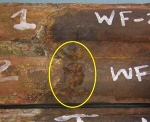
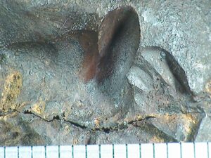
Figure 1 & 2 Significant metal loss in circumferential weld associated with cracking
An area of significant metal loss was evident in the circumferential weld. The metal loss had the appearance of grooving and exhibited a very smooth surface (Figure 2). A circumferential crack was located at the base of the metal loss which appeared to propagate partly into the membrane weld. Sections were taken through this crack so that the resultant section fell apart revealing a fracture surface, see Figures 3 and 4. The fracture exhibited no necking/deformation and was crystalline in nature, both of which are indicative of a brittle fracture mechanism, on a macro scale. On a micro scale, there was evidence of intergranular fracture, Figures 5 and 6.
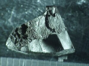
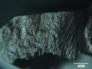
Figure 3 & 4 Fracture surface of circumferential crack
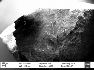
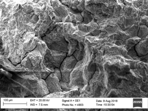
Figure 5 & 6 Fracture surface of circumferential crack
Upon sectioning, the crack appeared to follow the fusion line of the weld on the T22 side, see Figure 7. The cracking was slightly branched, and the direction of this branching indicated that the crack had initiated from the external surface, see Figure 8.
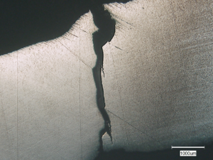
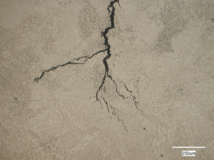
Figure 7 & 8 Branched cracking along fusion line
The deposit associated with the metal loss and cracking observed was found to consist of magnesium sulphate, magnesium oxide and iron oxide with small amounts of calcium sulphate dihydrate. Areas also contained significant levels of vanadium.
The chemical analysis of the parent materials and weld complied with their respective specifications. The microstructure throughout the entire weld and in the HAZ, close to the fusion line on the T22 side, consisted of quenched and tempered martensite. The hardness levels both in the weld and HAZ on the T22 side of the weld were significantly high with levels of up to 367HV. Although a post weld heat treatment is not specified for tubes with a wall thickness of less than 13 mm in ASME B31.3, a maximum hardness of 241HB and 225HB is specified for the T12 and T22 grades respectively. The high hardness levels observed could be due to high heat input during the welding operation. It was noted that there was a difference in specified interpass temperature between the PQR and the WPS (see appendix 1). Stricter welding parameters are required for higher alloyed steels, particularly with an increased chromium addition, since these generally have a greater hardenability and are therefore more susceptible to producing a quenched and tempered microstructure. This explains why a quenched and tempered microstructure was not present on the T12 side of the weld.
The evidence suggested that the through-wall crack was due to hydrogen embrittlement. Hydrogen embrittlement occurs due to the penetration of atomic hydrogen into high strength materials. Susceptibility to hydrogen embrittlement increases as the strength of the steel increases. The significantly high hardness levels measured in the weld and HAZ on the T22 side would have increased susceptibility to this mechanism.
Hydrogen embrittlement can occur during welding or from services that can charge hydrogen into the steel in an aqueous, corrosive or a gaseous environment. The presence of significant metal loss on the external surface of the weld, local to the crack and the appearance of the crack initiating from this metal loss may suggest that embrittlement had occurred due a combination of high hardness and exposure to the service environment.
The presence of a high concentration of sulphates in the corrosion product suggests that sulphuric acid was present. Sulphuric acid can react with the steel to form atomic hydrogen which can then produce the embrittlement observed. It is possible that the metal loss observed was attributable to sulphuric acid dew-point corrosion. Sulphur is present in heavy fuel oil and during combustion sulphur oxides are generated, a small portion of which becomes SO3. As the exhaust gas temperature reaches the dew point or lower, vapour-phase sulphuric acid forms (1). If the sulphuric acid vapour contacts the lower-temperature tube wall surface it may condense as liquid sulphuric acid and corrode the metal.
The temperature at which sulphuric acid first condenses varies between 116 and 166°C or higher, depending on the sulphur trioxide and water vapour concentrations in the exhaust gas (2). The critical factors governing sulphuric acid dew point corrosion include the presence of sulphur trioxide, the presence of moisture, and the presence of metal whose surface temperature is below the sulphuric acid dew point. The hydrated nature of the corrosion products suggests that significant levels of moisture were present in the environment. The dew point increases with sulphur trioxide content and moisture content (2). This corrosion mechanism is normally termed ‘cold-end corrosion’ since it generally affects the cooler regions of the system (2).
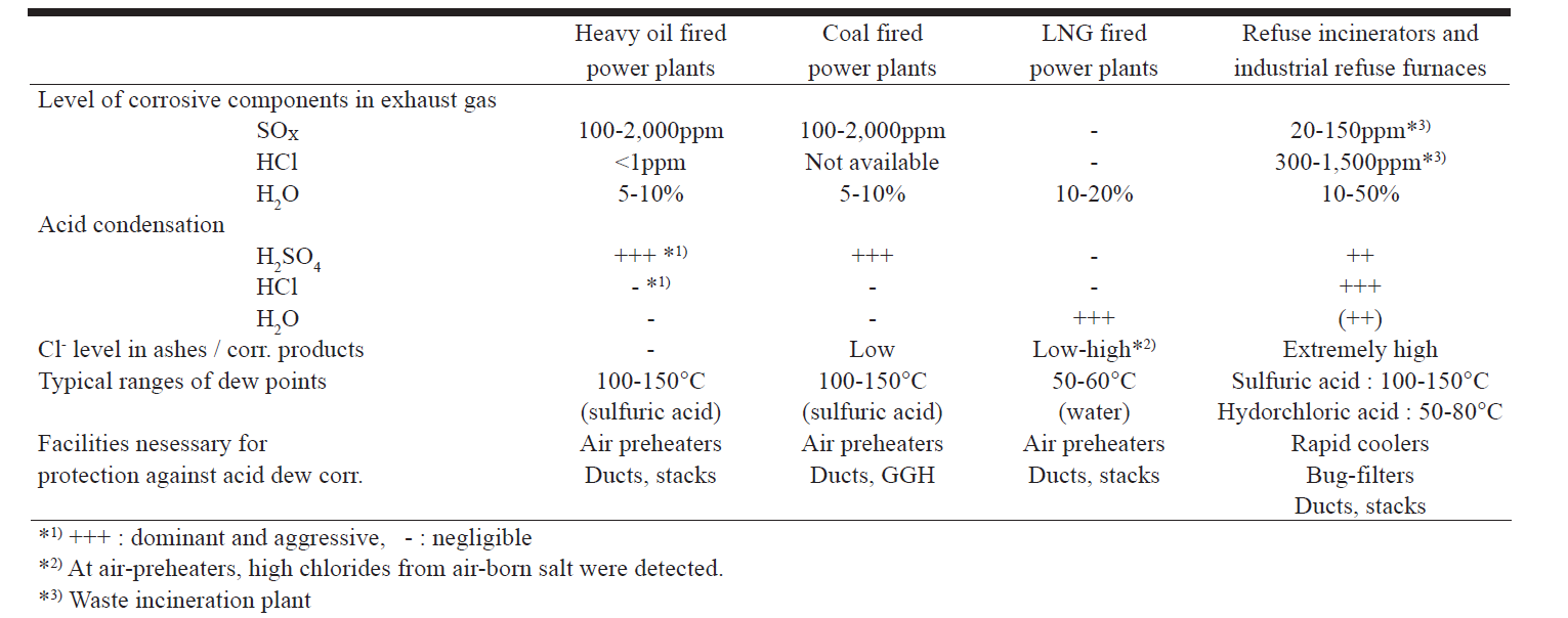
Dilute sulphuric acid (5 to 40%) is more corrosive than higher concentrations and as the H2O dew point is approached, acid concentrations in this range are likely (3). Table 1 shows the content levels of corrosive components in the flue gas of plants burning different fuels, principal acid condensations and the ranges of their dew points (4). The table shows that for a heavy fuel oil-fired power plant, sulphuric acid is the dominant condensate and is aggressive.
Table 1 Types of acid dew point corrosion (4)
Low alloy steels have shown superior performance to low carbon steels. However, care must be taken to ensure that a cyclic wet/dry operating regime occurs, especially during the early period of exposure. Continuous exposure in the wet condition can result in higher corrosion rates than may occur on low carbon steel (5).
Stricter welding parameters should be used for higher alloyed steels, particularly with an increased chromium addition. These materials generally have a greater hardenability and are therefore more susceptible to producing a quenched and tempered microstructure which can increase the likelihood of hydrogen embrittlement. Portable hardness testing, potentially coupled with replication metallography, is an effective way to ensure excessive hardness levels are not present. To eliminate corrosive quantities of sulphur trioxide it is necessary to operate the boiler at or below 5% excess air to the burners, to minimise air infiltration and to specify fuels with low sulphur content (2). Further, suitable measures should be taken to eliminate moisture within the furnace.
A failure analysis of this type is a valuable and informative tool to reduce the likelihood of a repeat incident which improves safety and productivity, reduces the risk of unplanned outages and enables evolution towards a better product.
References
- Nippon Steel & Sumitomo Metal. Sulphuric acid and hydrochloric acid dew-point corrosion resistant steel. S-TENTM
- The NALCO Guide to Boiler Failure Analysis. Robert D. Port and Harvey M. Herro. Cold end corrosion during service. Chapter 12. Page 143
- Materials Selection for Corrosion Control-Dew Point Corrosion. Materials Selection for Corrosion Control. S.L. Chawla and R.K. Gupta. ASM Handbook. 1993. Page 60
- New S-TENTM1: An Innovative Acid-Resistant Low Alloy Steel. Nippon Steel Technical Report No. 90 July 2004
- Components Susceptible to Dew-Point Corrosion. Corrosion: Environments and Industries. ASM Handbook. 2006. Volume 13C. Page 495